
I want to have baked chicken wings for lunch. Freshly baked chicken wings with sesame oil and celery, nothing can compare with a delicious nutrient-balanced lunch that powers me for another productive afternoon. But I only have one hour for lunch. Despite the fact that I live 5 minutes from the company, I still need 45 minutes to cook chicken wings and another 20 minutes to enjoy them. Although my manager is such a nice guy that he grants me some additional time for lunch when he hears the story, I still feel guilty for standing next to an oven doing nothing for 45 minutes. I need to find a way so that I can start cooking chicken wings by sending a command via Internet when I am still at work, and by the time I get home, the food is ready. That’s right, I want to have a chicken-baking oven controller.
The apartment that I live in has an electric range with stove on top and oven down below. At the very top is a control panel that has several knobs to control each heater coil and it looks like this:
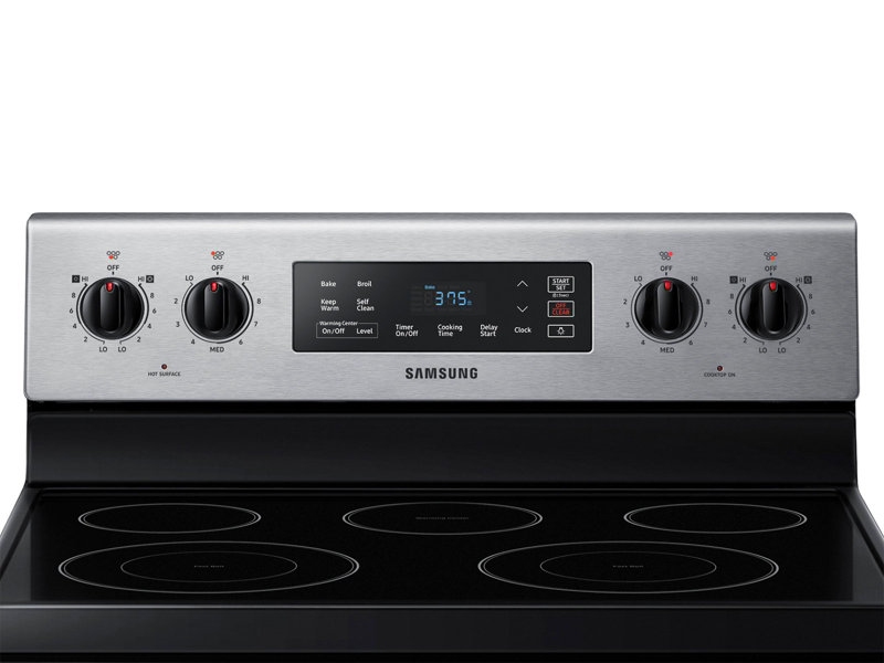
Because I’m renting the apartment, I can’t simply take the appliance apart and add some relays to control the on/off state of the coil. All I can do is to add some kind of mechanism to the control panel and turn the oven knob physically. And because I can’t damage the electric range at all, that means no drilling, the mechanism must be fixed to the control panel with magnet, glue or adhesive tape. The knob doesn’t require a push action before turning so it makes things slightly easier.
The plan is not too complicated. A coupler that fits the shape of the knob should be placed at the end of the controller so that when the coupler turns, the knob turns. A small motor, preferably a small servo, drives the coupler and provides functionality of angle control. An MCU with WiFi module is needed to program the controller, being it Arduino, RasPi or something else. I decide to start with a NodeMCU with ESP8266 because it’s cheap, Internet-ready and powerful enough for the project.
The first preliminary design is using the NodeMCU to power a servo that turns the coupler back and forth just to see if the servo has enough torque to turn the knob. The coupler looks like this:
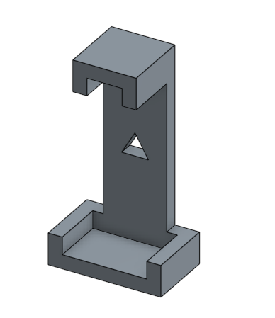
The front of the coupler fits the shape of the knob and the triangular cutout in the center allows servo to drive it. Very soon after the first test starts, I realize that the torque generated by one servo is simply not sufficient to turn the knob. Moreover, my servo can only turn from about 5° to 170° due to the nature of its design, but the knob needs to be turned by at least 270° otherwise I will have uncooked chicken wings. There are tutorials online that teach how to modify a cheap servo to make it turn 360° but I worry that it’ll mess up the servo library in the code and bring more issues to precise control. Using a stepper motor might be a great option as stepper motors don’t have turning boundaries and can be controlled very precisely, but they’re a little bit pricey (for me) and require more power and higher voltage (than 5V) to drive, so it’s considered a backup plan. A gearbox can be used to increase the overall output torque and partial-tooth gears can be used to extend the angle the the knob can turn. I combined gearbox and partial-tooth gears and come up with this design:
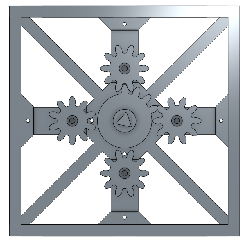
Each of the four gears on the sides is attached to a servo. The central master gear is turned by the four gears one at a time so that each servo only needs to rotate a little bit more than 90°. The pitch circle of the master gear is also larger than that of each servo gear, so that each servo can provide enough torque to rotate the master gear. The triangle insert at the end of the master gear fit in the triangle hole on the coupler so that the knob can be turned. Every piece is 3D printed and assembled together. The four servo gears need to work with each other in a timely manner so that they can “pass” the master gear from one to another, and this requires quite amount of calibration and code modification. The final prototype works like this (click to see animated gif):
Everything works perfectly until I fix the housing to the range control panel with double sided tapes. The housing can hardly keep itself in position once the servos are working. The torque applied on the knob is also applied on the housing due to Newton’s third law, and because the double sided tape can’t offer good resistance along the direction parallel to the panel, the housing tends to rotate against servo gears, bringing troubles to gear meshing and causing more torque applied on the knob and the housing.
I decide to stop the project in the end as I can hardly think of a plan to comfortably fix the housing in position without damaging the appliance, on the other hand, this project doesn’t seem to be very useful because I can easily install an MCU and relays inside the oven and control everything from the Internet without bothering any mechanical design issue. But when I look back at it, although being an “unnecessary” project, it does provide me better understanding of how important the initial design is. I should’ve thought about the possible problems at the beginning and picked a different approach.
Lessons learned, time to order some chicken wings for lunch.
[qrcode]